Thursday, April 12, 2012

Credit where Credit is Due!

Day 53

Setting the Record Straight!

Part of the project grant was specifically to cover my participation in Smeltfest 2012, hosted by Lee Sauder at his Germinal Ironworks outside Lexington Virginia.
Lee, assisted by his close friend and smelting partner Skip Williams, started investing historic bloomery iron smelting methods in the 1990's. They were initially inspired by African models, then worked backwards to establish a functional and predictable technique.

Sauder & Williams, pulling a bloom from their 'African Queen' furnace.
Frontier Culture Museum, Stauton VA - 2002

I had the good fortune to meet Lee and Skip in Fall of 2002. I had only undertaken two smelts at that point, both unsuccessful. They were extremely generous with their knowledge and folding my small group (other members of DARC) into their demonstration. Although we did little more than help with some of the 'dirty jobs' I certainly learned an immense amount. They had already determined the critical high volume air flow required to correctly produce dense iron blooms. By the point I met them, they had published their research both formally and inside blacksmithing circles.

Thanks to the wonders of the internet, the Spring 2004 smelt at Wareham had a special guest, Michael McCarthy from Cooperstown NY. Mike had been smelting at the Farmer's Museum, basing his furnaces on Colonial American models. He was actually on his way back home from spending a week building and operating a Japanese tatara furnace. Although yet again tour smelt was a complete failure, a solid friendship was struck up.

Mike would organize the first Early Iron symposium at the Farmer's Museum in Fall of 2004. This gathered together Lee & Skip, Mike and myself as demonstrators, each building and operating a furnace from our various traditions. My (quite unplanned) contribution was a Norse style short shaft.

the "Gangue of Fer"
(L-R) Sauder, Williams, McCarthy, myself (back)
Early Iron 1 - Cooperstown NY, 2004

Late Winter of 2005 would mark the first of the invitational Smeltfest events hosted by Lee. Initially this was just the small group of us, concentrating on some specific aspect of furnace construction or smelting method.
Over the years a number of functional problems have been proposed and tested. These methods have then been incorporated in the continuing work of all three teams. A growing group of other enthusiasts have been included and have contributed. The core these days includes Jesus Hernandez, Shelton Browder and Steve Mankowski. Smeltfest has been fortunate to have include a number of wide flung guests on a more irregular basis, including some that have travelled a fair distance to participate. (Recent years have included Jake Keen, Tim Young and Therese Kearns from England, Jeff Pringle from California.)

In truth, the Early Iron group acts much like a think tank - with a solid practical workshop aspect. Evenings are spent in brainstorming ideas, with the raw energy of being gathered from isolation into a group of fellow enthusiasts. Days are spent testing out suggested concepts. The combination of experiences, interests and personal skills provides a unique and often intense, learning experience for us all.

My single largest contribution to the overall endeavor has been with documenting and publishing the discoveries. Almost always I am *not* the originator of these ideas. In practical work, I am typically just a 'worker bee' rather than a team leader.
I do make every attempt to make sure credit is given where credit is due.

(This clarification arose from some secondary mentions of yesterday's blog post. Tomorrow I will expand on those additional comments.)

Tuesday, April 10, 2012

Crossover - Slag Rings in Archaeology?

The impact of an OAC project grant may extend well past the intended application.

My interest in bloomery iron started with the historic process of making the iron. Although there are some scattered living traditions (notably in Africa and India), these are fragmentary at best. For Europe, the technology of making iron has changed significantly since 1000 AD, with several pronounced shifts in method, equipment and type of metal produced. In attempting to re-discover what is a 'lost' tradition, modern researchers and practitioners are guided by very limited archaeological remains alone.
The best experimental archaeology may offer insights into how to interpret what may be puzzling artifact remains.

***********

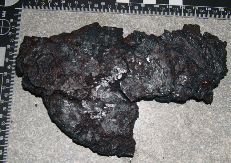
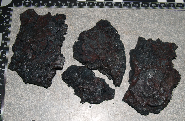
These are some shots of slag rings recovered from two of our recent smelts (at Smeltfest 2012, Lexington VA, March 2012)

Lee Sauder has been using a heavy forged copper tuyere on all his smelts for the last several years. I'm not entirely sure just why he came up with this innovation. I believe it was in attempt to find a durable solution to the problem how the high temperatures inside the iron smelting furnaces were melting off the ceramic and steel pipe tuyeres then in use.
His tuyere was forged from a solid copper plate roughly 3/8 inch thick. First the piece was cross peened along the long axis to both spread and thin the rectangle into a triangle shape. Then the resulting form was wrapped into a cone. The finished cone is roughly 2 cm ID on the furnace end, about 4 cm ID on the bellows end. The piece is maybe about 40 cm long altogether. The closing seam is just butted together (not fused or entirely air tight).
Lee's clay 'medium shaft' production furnace.
The conical forged copper tuyere can be seen to the right

In use, what happens is that the heat the tuyere end is subjected to quickly travels back to the larger end exposed outside the furnace. The combination of radiation to the outside air, and rushing cold air down the inside surface, all combines to keep the tuyere end well before the slumping or melting point of the copper material. The result is virtually no effect to the the copper tuyere, even after many firing sequences. I think Lee has used this same tuyere for something like 30 smelts, with no damage at all!


As the rings would sit against the furnace wall


Inverted, showing the slag and ore fragments on the top surface

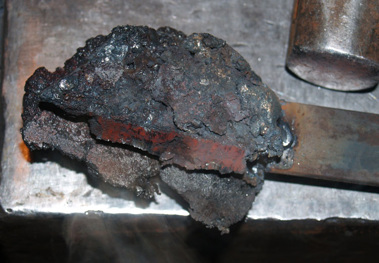
The slag will harden to a shell around the tip of the tuyere. These rings do not solidly attach fuse to the copper, normally hand pressure will break them clear.
You can see that both the internal and external diameters are indicated in the slag rings.
You can determine the upper and lower surfaces, with the heavier accumulation on the 'up' side of the tuyere in the furnace.
You can get some estimate of the tuyere angle. The slag has formed proud of the furnace wall, so if you assume the inner wall to be vertical, the inside surface does record the tuyere angle.


Inner surface (inverted here)
The inner diameter and thickness of tuyere can be determined.

Both the rings show cracking in roughly the same place. I think this is an effect of the cooling rate of the slag and the shape of the rings. One of the collected rings had in fact separated into two pieces ( the ring on the left in the images above).

One ring was broken into two pieces

We have worked with ceramic tube tuyeres as standard here for the last while. These are uniform, cheap and fairly durable. They also are quite obvious as a physical remain. Same goes for the iron (steel pipe) tubes we have also made use of. As the iron tuyeres are consumed with every smelt, I don't think that this material likely for VA process - just from a practical standpoint. (wasting iron to make iron?)

Copper tuyeres might be another mater. They would be 'relatively expensive' as objects, but because of their proven durability would be worth the investment for repeated smelt operations. The copper would be too valuable to discard, likely just being cut up as raw material for bronze production at the end of their smelting use. Any finds of copper cut to rings as a bronze related find? It would be the easy way to re-cycle the material.

Anyway, the slag rings are quite distinctive. Lee said he gets these every time. Worth a check against remains?? (Kevin Smith had mentioned that he had recovered some semi circular slag fragments from his excavation of an 'industrial' VA iron smelting site at Hals in Iceland. It will be interesting to see if these modern pieces in any way resemble his artifacts.)

We messed with using a copper tuyere a long while back, but at the time I did not have any heavy copper bar or sheet. The copper tuyere I made up was only 1/8 thick material, and did not transmit heat fast enough to keep the end from melting back to the furnace wall. This would have certainly produced some droplets of copper into the slag someplace. Perhaps another signature to look for in the archaeology?

(Modified from the initial posting on Hammered Out Bits)

Monday, April 9, 2012

A Week in the Forge

Day 50

The shop work this week has primarily been directly converting blooms to bars / plates.
As a fast overview of what was accomplished:

Tuesday April 3
# 15 - Smeltfest 2006 Smelt A, hematite in medium shaft furnace
Small fragment @ 559 gm
Part way through the welding process

Finished bar @360 gm
Spark test shows mid carbon content

Tuesday April 3
#49 - Slag Pit 2 - taconite in short shaft with slag pit
Continue work from March 7

Bloom pieces @ 432 and spring steel core (total 590 gm)

Welded billet ready to forge to blade

Wednesday April 4
# 30 - Smeltfest 2008, DD1 in medium shaft with blow plate
Lacy section @ 625 gm


After compression under press


Finished bar @ 393 gm

Thursday April 5
#16 - Smeltfest 2006 Smelt B, hematite in medium shaft
Main bloom @ 1770
Bloom at preheat stage

Larger plate cut to remove fractured half (@463 gm)

At the third weld stage
Finished bar @ 357 gm

Friday April 6
Completion of object started March 29 (polishing & finishing)
This object is a gift, so details to come later.

Saturday April 7
#8 - Smeltfest 2005, Lexington in Econo-Norse
Section of full bloom (included cutting) @1426 gm


After compression steps on press


forged to 1/4 inch thick plate

Other project work:

Monday April 2
Finished repairing / installing engine exhaust system for hydraulic press

Monday, Wednesday, Friday, Saturday
Blog posts.

(Of course there is the normal daily 'shop office' work of accounts, clean up, communications.)

Just in case you were wondering what I've been doing.
Half of Sunday was taken up with a customer consult on a project for later spring.


Saturday, April 7, 2012

Listening to the expert


If there is one name you will see over and over here, its Lee Sauder.

Lee, working with his smelt partner Skip Williams is most certainly the single most experienced bloomery iron worker in North America. I'd lay money he's the best counting the Europeans too. He is one of the other core driving members of the recent 'Early Iron' movement. There is no doubt that had I never met him, I would have given up on my own efforts to understand Norse iron smelting years ago.

Bearing in mind yesterdays long description of a working series with a bloom (and what went wrong) here is a link to what Lee has written as advise on the process :

Sauder's Bloom Forging Hints

If any readers wish to ease into working with bloomery iron, but are uncertain about plunging right into furnace construction (and the uncertainties of iron smelting), Lee also sells partial bloom sections and worked up bars :

Bloom Iron Sales

Home Grown, Organic, Free Range Iron Fresh from the Furnace!


Friday, April 6, 2012

A typical work session...

Day 49

Two things define a typical 'project day'.
First, there is the mornings, normally spent at my desk on the computer. This covers normal communications, business record keeping, research, - and preparing, writing and laying out blog postings (like this one).
Second, there is an afternoon session in the shop. This includes equipment set up - and actually working at the forge.

What that might look like? (1)

I have been trying to document all the ongoing work on the project. There was time spent cataloguing all the blooms, fragments and partial bars from a decade of iron smelts. There is normally also photographs and records kept on the finished bar produced on a specific work session. I've also been trying to keep the camera handy to take images of specific aspects of the ongoing work. Now and again I try to take enough images of the whole session to document the entire process of bloom to bar, set by step (2).
Now this is not exactly easy to accomplish, being both worker and photographer at the same time. Working the metal is very time dependant, specific heats being required for various processes. The camera also 'sees' deeper into the infra-red than the human eye, so records things much differently than what you might see if you were standing in the shop. Another problem is capturing a crisp image in the dim light necessary in the workshop. Flash images are crisp, but at the cost of washing out the visible colour of the hot metal.

So, this is what I did on the workshop session on Thursday April 5 ...
(click on any image for the full sized version)

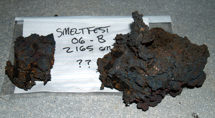
Bloom - Smeltfest 2006, Smelt B
Ore - Granular Hematite
Furnace - Medium shaft, standard set up
Starting Weight - 2165 gm
Bloom Condition - somewhat granular, likely mid carbon content
Objectives - 1) Working with a larger sized bloom
2) Creation of large plate with intentionally ragged edges (for use creating a bowl form)

Error Number One I have been looking up the details of the bloom composition AFTER my working sessions.
I should have taken more care on selection of the base bloom for the specific objective (!) The higher carbon blooms are naturally more likely to fragment when working, and are not the best suited to the specific purpose in mind here.


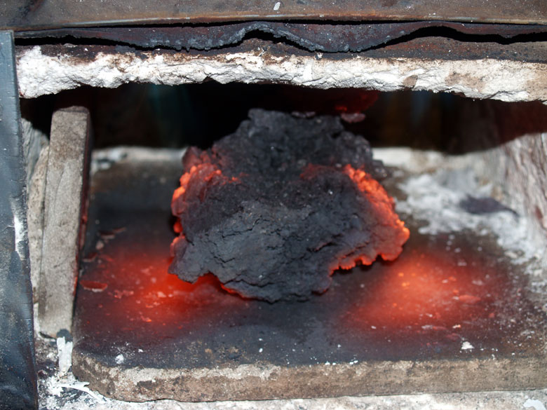
On examining the starting bloom, it was seen there was a fragment on one end only loosely attached. This piece was worked loose and set aside for later processing. The larger piece remains was weighed to 1770 gm.


This piece would still fit into the double burner propane forge for pre-heat. The shot above is taken just after the forge itself was lit, so you can see the internal chamber itself has not come up to operation temperature.
The more important function of using the gas forge is to allow for a generous heat soak period - to ensure that the heat has penetrated through the whole mass. This continues while I am setting up the coal forge for the work session. This normally takes about 30 minutes to clean, screen, light and get through the coking cycle into a correct condition for forge work.


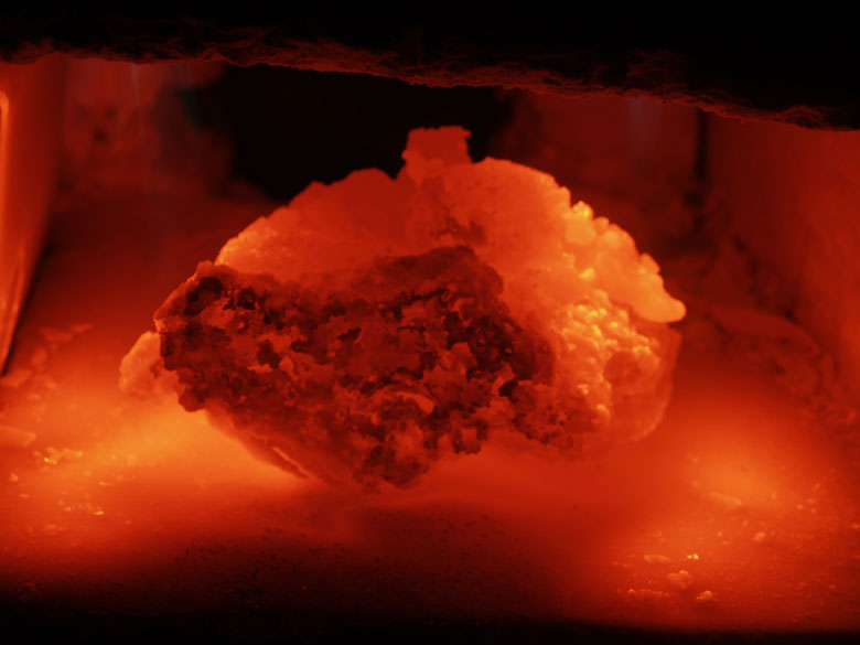
This is the condition of the bloom after 20 plus minutes heat soak. This propane forge will at best produce a 'bright orange to almost yellow' heat level. Although this is fine for general forge work, it is not quite hot enough to weld.
So now that the coal forge is ready, I transfer the bloom over to the (much hotter!) coal fire.


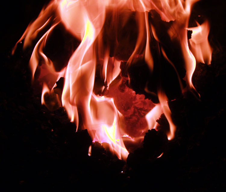
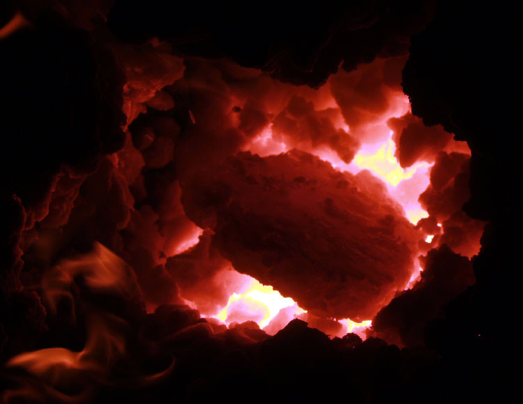
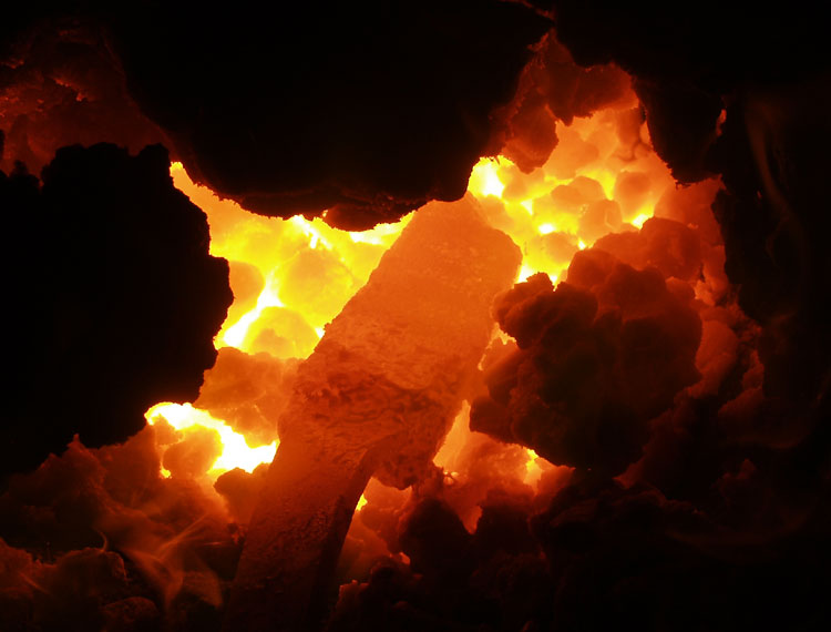
In this available light image, you get some idea of one of the first problems, which is simply fitting a bloom mass of this size into my existing coal forge - and effectively heating it. My fire box is a fairly large one, roughly 9 x 7 x 6 deep. I can easily get the *depth* of fuel for a hot fire. The problem is getting even heat around both edges of the large bloom mass. The forge is set up with a standard bottom blast, which means the primary heat direction is from the bottom as well (watch for this and its effect later).
Care is taken to increase the heat of the mass relatively slowly. The piece is constantly turned and flipped so there is the best chance of getting the whole mass to an even temperature. The intent is to get the mass up to welding temperature for the compression phase.

The first forging steps are carried out on the hydraulic forging press:


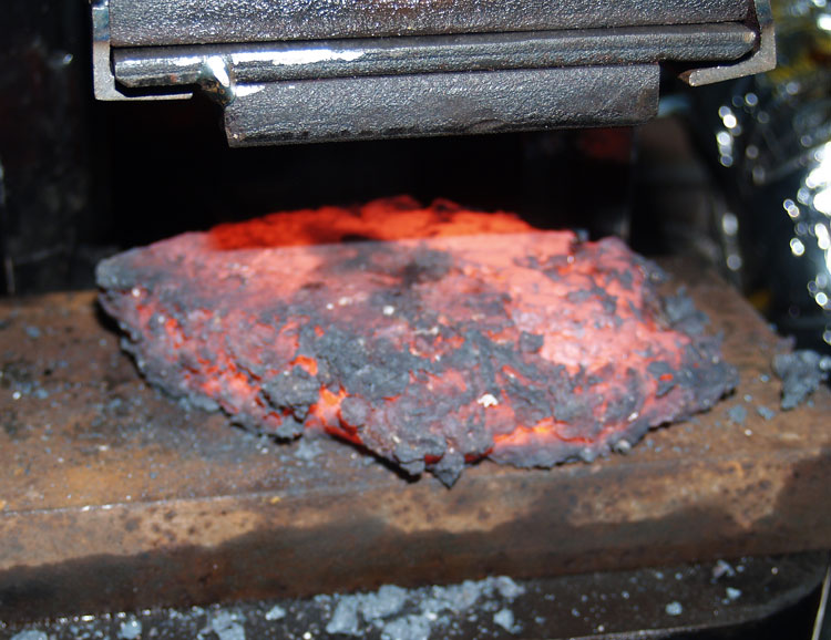
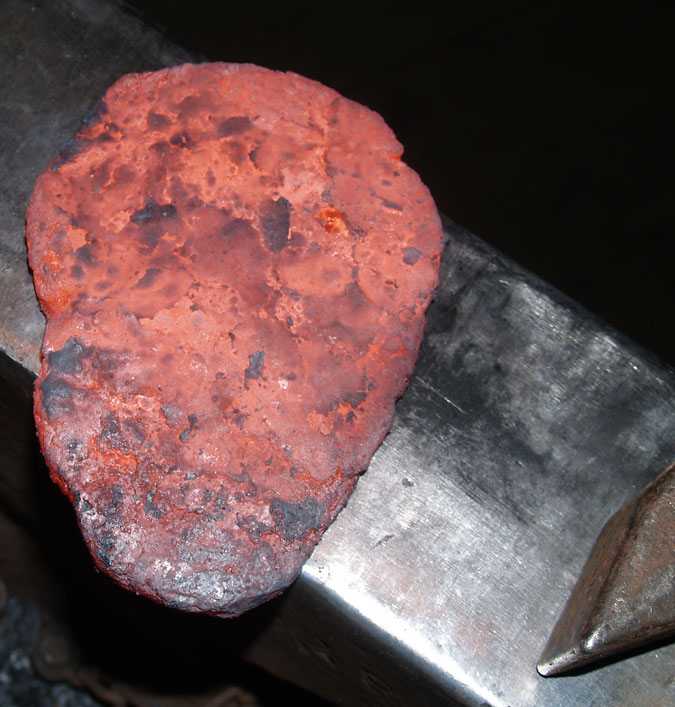
The first compression uses the larger flat plate die, also with the larger full sized bottom plate. The bloom is compressed along its natural top to bottom axis, with the flatter (top) side placed down. With quick work, it is then flipped and compressed again. At this point the 'cake' is roughly 3/4 inch thick, and still very ragged, especially on the edges.
The huge advantage of the press is that it is *squeezing* the often fragmented bloom mass together, rather than *pounding* it, as would be the case using my air hammer. This is especially important when working up the more granular higher carbon blooms. (The hematite blooms are almost like solid pieces of brown sugar in texture.)


The cake is placed back into the coal forge and brought up to welding heat again. Now the more compacted shape makes for more even heat penetration into the centre. At this point the piece is not so large that there is not fairly even heat distribution from the top and bottom of the fire.


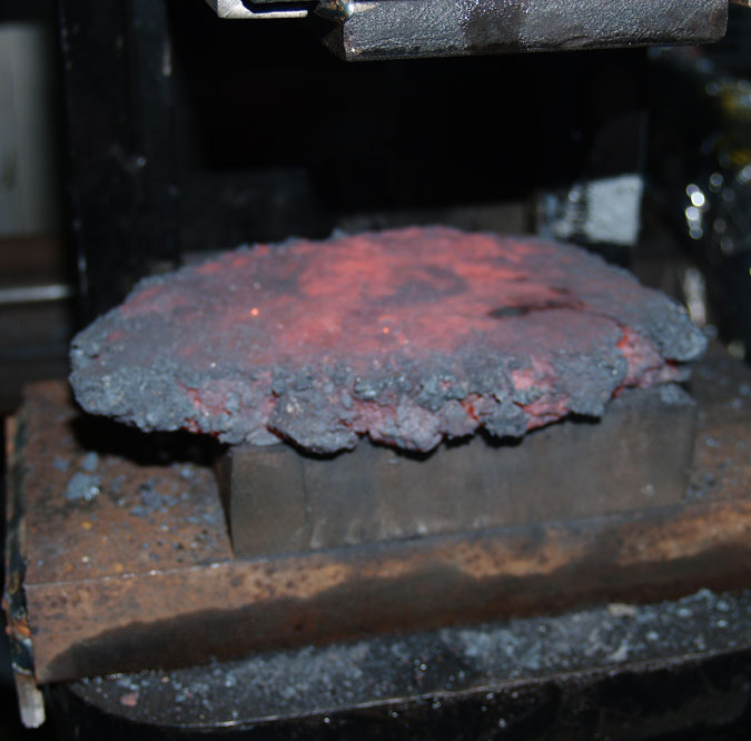
Taking into account the action of the press, a second bottom plate is added. The cake is compressed down closer to 1/2 inch thick.

Back to the forge for another series of welding heats. This work is done with the hand hammer at the anvil. The ragged edges seen in the photo above are gently welded in towards the centre. This is done about 1/4 of the circumference at each welding heat. (A total of 5 heats were taken here)


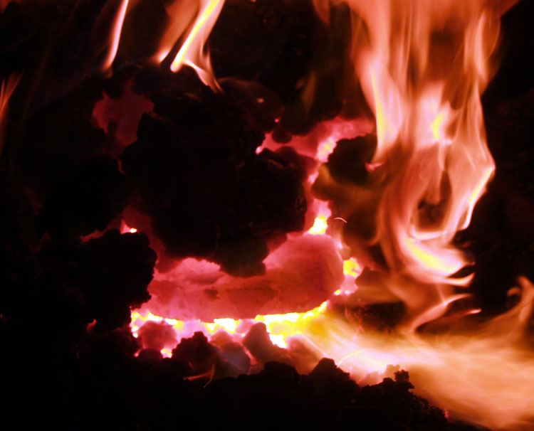
This shot is heating prior to the last compression step. You may spot a developing problem. The size of the plate is now large enough that it effectively blocks the air blast from the bottom of the forge, not letting enough oxygen into the top layer of fuel. There is now a very marked difference in the heat being applied to the bottom surface, compared to that on the top.


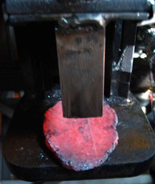
The narrow 'slot' die has been placed on the press. The surface of the plate is worked over (total three compressions on the first side, four on the second). At the end of this step, the plate has been reduced to about 3/8 thick.


(there is a gap in the images here)

Next the work shifts over to the air hammer. The plate after compression is a rough oval. As the intended application is for a bowl, a more symetrical shape is desired. For that reason, the placement of the piece on the air hammer is with the long axis of the dies running the same direction as the long axis of the metal. Due to the combination of metal size and small die size, only one half of the metal can be worked at a time. So there are a number of heat / work cycles required. An attempt is made to start each cycle back up to welding heat.

Error Number Two Remember that higher carbon metals are *much* more prone to overheating.
My attention got pulled away (by something) and I ending up letting the thin plate get drastically overheated at one point. The fire itself also was starting to perform less consistently (3).


The end result here was that I ended up burning out a small chunk of the plate. As well there were some serious flaws / cracks running through one side of the surface.


Sometimes you just have to know when its time to switch gears.
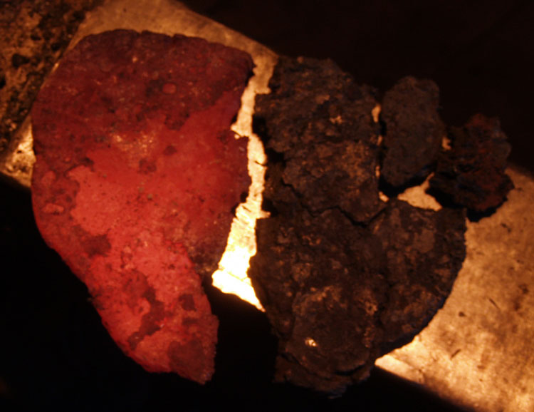
With almost all the damage on one half of the plate, I used a hot cut to divide the plate into roughly two half sections. The slightly larger piece, now at roughly 6 x 3 1/2 x 1/4 inch thick (684 gm), looked solid enough to continue working down towards a possible (smaller) bowl later.


The major cracks on the other section were used like score lines to break up the piece. This piece was roughly the same dimensions, but with the bite out of one edge, the weight was 463 gm.


These were combined roughly in the relationship seen here. The two larger fragments making the two outer surfaces, the smaller plus one little piece (broken off earlier) placed into the centre.


At this point I'm into a sequence that I have used a number of other times working up smaller bloom fragments.
The pieces are stacked, and tack MIG welded on one end to a mild steel bar and to each other. There is a total of 499 gm of bloom material. (This time I remember to weigh the handle separately!)


I've had a bit of a break, considering how to continue and cooling pieces to weigh and record. I also pull the bottom of the fire apart to clean it, and set up a new coke 'cavern' for proper forge welding. This is also much more familiar territory for me - a process much like I employ for layered steel. First there is a light fast hand weld to secure the pieces. This is followed with a heavier series of hand welding to make sure the pieces are well solidified. Although it is true bloom materials can contain a lot of glassy slag, I figure adding a bit more flux (borax in my use) can't actually *hurt* anything. I take care to get the ragged edges in the stack folded and welded in. Final compaction and drawing out is done on the air hammer.


The result is a small billet, roughly 1 1/2 x 8 x 3/16 inches. You can see that there is a prominent crack along one surface.


Deciding to work with the flaw, rather than against it, I use the hot cut to divide the billet along the crack. I had hoped to just score and fold (not normally what I do btw). The pieces actually separated. Perhaps not the absolutely wisest move, I decide to use a more 'japanese' technique - just balancing the two pieces in the fire and heating from the bottom. (Hey, it works for my friend Jesus Herandez...) Maybe a bit surprisingly, I manage to get a a good heat and successful weld. Under the air hammer, I work more aggressively *against* the last weld direction (so on the edges).


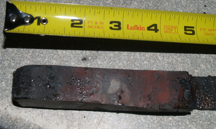
The end result of *three hours* is this finished small bar. Rough size is 5/8 x 1 x 4 1/2 inches at 357 gm.

Calculating the bloom to working bar loss is a bit rough here.
From bloom to cracked plate, the numbers are 1770 to 1223 = 69% return (so 31 % loss)
From plate pieces to bar the numbers are 499 to 357 = 72 % return (so 28 % loss)
Overall bloom to bar works out to 50% yield
(but bear in mind the material lost to that overheat)
(Thanks Neil!)


Notes

1) Important Note!
Remember that the purpose of the whole project is for me to accumulate some (necessary!) experience converting blooms into working bars, and hopefully then into objects. Obviously what I've documented here is very much a *learning process* and should not be considered the 'best' way to accomplish a given task!

2) One other aspect of these images : The original higher resolution images have been transformed via Photoshop into web format detail. Generally the image size has been modified to roughly 8 x 10 inches. This, combined with the various camera positions, makes the scale of the individual images vary considerably. Some images are shot with scales, so remember to use those to determine relative sizes. For the images shot on the anvil surface, the width of the anvil is 4 1/2 inches.

3) Lee Sauder uses a side blast set up when he works blooms. The clear advantage here is the the air flow comes in from one side edge (so spreads more evenly top and bottom over a cake or plate shape. More significantly, there is a lot of slag generated in the bloom to bar process. With a bottom blast, this material oozes to the bottom of the forge, effectively blocking part of the air blast. As this debris increases, the effect is to create hot jets of super heated oxygen. Effectively these act like small cutting torches inside the forge, which with poor attention (!) can have the effect of over heating (burning!) just part of the metal contained within the forge.


PS - Crunching the images, writing and formatting this essay has taken roughly three hours. I did need a bit of a break from a 'good week' at the forge. After lunch I'll get back out there and may have something to report on later!

If anyone is counting, today would be the 29th 'standard work day' on the project. Thats counting like it was normal days with weekends off.
In actual fact, according to my project diary, today counts as the 48th full day I've worked on the project.

You're getting your money's worth...

Wednesday, April 4, 2012

Pressing On

Its NEVER as simple as it seems...
A saga of poor design and failed materials

Day 47

In my original proposal, I had included two weeks for shop conversion and preparation directly for this project. Along with laying out the space to dedicate it to project work, I had included some time specifically to finish setting up the hydraulic forging press. (I had purchased and started working on the building the press over two weeks before I even knew I had been awarded the grant.)
You know what they say about grand plans and good intentions...

The 30 ton hydraulic forging press is critical to the bloom to bar work. As I have mentioned before, my 50 lb air hammer is simply too small, both power and die size, to work the blooms. This is especially true of the larger ones, in the 7 - 8 kg range. These masses are roughly the size of half a basket ball. Imagine attempting to balance, and compress that, on a die surface only 1 1/2 by 4 inches.

One of the major problems I have encountered with installing the hydraulic press is with the engine exhaust. The press uses a 5 hp gasoline engine to drive the hydraulic pump. The way I re-worked the original log splitter equipment into a forging press places the engine exhaust such that it would end up blowing straight on to the operator. Hardly ideal.
The solution was to install a system of piping that would both contain and vent off the exhaust completely outside the building.
Which has proved far more difficult that I expected.

Exhaust System, mark 4

The problem has been two fold:
1) Leaking fumes from the various joints between fittings
2) Vibration from the gas engine

My initial idea to combat leaks was to eliminate / reduce the number of joints, and tape over all the joints. I normally use a thin aluminum tape, designed for heating duct work, around the smelting furnaces. The aluminum has a quite high melting point, and easily crimps over irregular surface.
The problem with the tape is that the resin based adhesive burns off at the kind of temperatures that the hot engine exhaust produces. Especially close to the exhaust port - which also happens to be the place most of the pieces are stuck together.
(The engine port is roughly 1 1/4 diameter. I've modified the original cover with a short piece of pipe. Next I made up an aluminum conical fitting that expands out to 3 inches. To that is attached commercial fittings : a 3 inch adjustable elbow, a short section of 4 inch duct pipe, then a 4 inch adjustable elbow. All have joints to secure.)
So the first tape job lasted about 15 minutes.
I pulled off this tape, re-applied fresh stuff. I wound a length of thin wire over the whole section, bracing over all the joint segments. Then I put another layer of tape over the wire.
That tape job lasted about a hour.

On the end of the elbow, I had placed a length of flexible aluminum hosing, normally used for clothes dryer vents. Although this material was a bit thinner than I would have liked, it also came as a single 20 foot length. I could run the end right out the shop door.
Too flexible and too fragile - the vibration tore up this hosing about an hour into the press operation.

I was getting pretty frustrated at this point. I'd spent much more time on fixing the venting than doing forge work. I decided to give up and head into town. Brent at my local McDonalds Home Hardware (in Dundalk) suggested a fiberglass repair tape intended for fixing mufflers. "How good does this stuff stick" says I. "I used it one time for an emergency road repair, then had to cut the pipe off because I never could remove the stuff." says Brent. "But its expensive..." Like $4 for 36 inches. He has one package, which I buy, and tell him to order me another (which turned out to have been smart).
I also get a different type of expandable aluminum dryer hose, this less flexible and considerably heavier weight. This is the stuff I use on my forge blowers in the shop. It is twice as expensive, and only half as long.

Next day, I pull off the round two tape, lay down one layer of new aluminum, re-bind the wire over it. Did I mention that this fiberglass stuff needs heat to set and cure it? So I have to turn the engine on, breathing exhaust and trying not to burn my fingers. I cut and set the repair tape. Of course when it is warm, the damn stuff slides all over the place. I lay down another layer of aluminum tape to hold the fiberglass in place until it cures. Turn off the engine, attach the heavier semi-flexible hose. Now wait for the fiberglass to cool and set.

This was all the week of March 5 - 9. By that point I was supposed to be focused on bloom forging - not equipment. I had scheduled a workshop day with blacksmiths Kelly Probyn-Smith and David Robertson for Thursday March 8. Kelly had to cancel on short notice. David did come over, and we spent about four hours (a long work session for forge work!) experimenting with the hydraulic press.
Only to find that although the fiberglass tape held well, the hosing did not. Two tears in it, both from the vibration.

At that point I had the OABA demonstration to prepare on Friday, the demo of the Aristotle furnace to mount Saturday. I was leaving for the combined Smeltfest and research trip on Tuesday crack o dawn. I had not done any serious trip planning or any packing for that either.

Press Venting - complete

(Leaving out the two days spent figuring out why the brand new engine will not start. Read as 'water in the gas, stupid')

So on the way home from Smeltfest, I stop at the Shelburne Home Hardware, and get more elbows, several lengths of heat vent pipe. (No, I do not have measurements)
I get 'serious' on the vent installation. More fiberglass tape on all the joints right at the press. All joints secured by screws. All joints in the whole system taped with aluminum. Solid pipe throughout. Pipe is supported on bungee cords to dampen vibration.
Add another day because I'm short on the pipe required.
Add two days (one for snow, one for rain) because I have to climb up on the roof to fit the vent cover through the upper shop wall.

You can see the finished system runs the exhaust up the side of the press, then over to the shop wall. Over the top of the lower section (12 inches of concrete) to the upper wooden and metal sheeting covered portion. There is a standard dryer vent that now exhausts (most all) the fumes to the outside. And some of the noise too.

Total time expended : better part of a week's work sessions.
Total additional cost : over $100


Movable base plates for the press

Yesterday, along with some very good bloom forge work (report to come) I made up a pair of extra base plates for the press. I just happened to have a piece of 1 x 6 plate in the shop. It proved just long enough to make three individual base plate pieces. The largest covers pretty much the entire press base, serving to raise the work surface up an extra inch. The smaller pieces fit nicely under the flat die I had already made for the press head. These two new base plates both have flanges on their edges (not clearly visible here) which solves the vibration problem I was having with pieces just set on the press base frame.
The bottom edge of the tape seen on the right side of the frame indicates the location of this flat plate die with the ram at full extension. You can see that with the two new base plates in place, the flat die will actually come to contact before the ram is at full extension (remember that there would be a piece of hot metal in there too.)

Monday, April 2, 2012

Day 45 (!)

There have been few postings of late. Returning from Smeltfest, some fairly annoying work on the hydraulic press, one more bloom converted to bar (more on that later).

Although not normally required in the progress of an OAC Crafts Project grant, I personally consider communications an essential element of any research project - especially one related to recovering lost skills.

Although more a related topic, than part of the project at hand (Bloom to Bar), two of the lectures I will be giving inside the grant period are on the 'Vinland' experimental smelting series. This work was undertaken in 2009 and 2010. The public lectures are formal presentations, which describe the objectives of the experiments, plus the results. The first was given this weekend (March 31) at Forward Into the Past at Laurier University, Waterloo ON. This was in some ways a trial run for the presentation at the more academic International Congress on Medieval Studies conference at Wester Michigan University, Kalamazoo MI (on Thursday May 10).

I have placed a converted version of the power point presentation that accompanied my delivery up on my iron smelting documentation.

The title of the formal paper is : Towards an Iron Smelt in Vinland - an experimental investigation

PS - Preparing that presentation took most of two days last week. Today I will finish installing the venting system to exhaust the gasoline engine on the hydraulic press. Then its back to bloom work!

February 15 - May 15, 2012 : Supported by a Crafts Projects - Creation and Development Grant

COPYRIGHT NOTICE - All posted text and images @ Darrell Markewitz.
No duplication, in whole or in part, is permitted without the author's expressed written permission.
For a detailed copyright statement : go HERE